


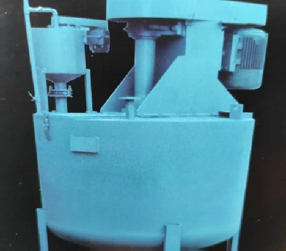
Pouring Mixer
2. After welding the bracket onto the welding tire, process the flat reference surface
3. Install the bearing seat on the mounting surface and perform a one-time boring process on the bearing seat body
4. Specialized drilling die for drilling
New technology for pouring mixer:
1. Welding of steel plates for barrel body and bracket
2. After welding the bracket onto the welding tire, process the flat reference surface
3. Install the bearing seat on the mounting surface and perform a one-time boring process on the bearing seat body
4. Specialized drilling die for drilling
5. All parts of the support are interchangeable
6. 2-hour air test after assembly
Function: Ensure accuracy, smooth operation, low obstacle rate, and easy maintenance.
Purpose:
The JQ170 diversion pouring mixing tank is a material mixing machinery used for the pouring of aerated block blanks, located above the mold.
Main technical parameters
1. Maximum external dimensions: 2.200 × 2.200 × 3.310 (excluding pouring arm)
2. Mass: 2890 kilograms
Electric motor:
1.Model: YVP225S-4
2.Power: 45Kw-110Kw
3.Speed: 1440r/min
4. Cylinder volume: V=4 ㎡ (inner diameter of cylinder is Φ 1.7m)
5. Mixing forms: spiral, double-layer cross blade, centrifugal
6. Mixing speed: 680-980r/min
7. Pneumatic butterfly valve: D671J-10-2008
Structure
The diversion pouring mixing tank consists of two parts: the mixing tank body and the pouring arm.
1. The mixing tank is composed of a cylinder, an electric motor, a mixing shaft, mixing blades, and a guide vane. Adjusting the distance between the guide tube and the bottom of the cylinder can change the mixing effect. Experience has shown that it should generally be controlled between 130-180mm. The smaller the distance, the more obvious the stirring effect, and the greater the required motor power.
2. The pouring arm is a rigid structure, and the material dropping from the pouring port is controlled by a pneumatic butterfly valve.
Working principle
1. The guide pouring mixer adopts the principle of guide tube mixing, with fast and uniform mixing speed. The stirring power is an electric motor, which rotates counterclockwise (when viewed from above) to drive the stirring shaft and blades to rotate, causing the material to churn up and down in the cylinder and guide tube, achieving the purpose of stirring.
2. The pouring arm is located above the mold. After the material is stirred evenly, the pneumatic butterfly valve is activated, and the material enters the pouring arm to pour into the blank mold.
Installation
1. Place the mixing drum flat on the prefabricated foundation and add rubber shock absorbers on the four joint parts.
2. The pouring arm is installed at the lower part of the feeding port of the mixing drum, and a pneumatic butterfly valve should be installed between the mixing drum and the pouring arm. According to the process layout requirements, the direction of the pouring port should be adjusted on site.
Trial operation and adjustment
After the installation of the mixing drum, attention should be paid to adjusting the following components:
1) Tension the motor belt;
2) Tighten the bearing cover of the mixing shaft to seal the felt gasket properly;
3) Arrange the pouring arm according to the process and adjust the pouring port.
Trial operation
1) The motor rotates clockwise and runs normally.
2) The mixing drum is stable
3) The stirring shaft rotates without jamming or abnormal noise.
4) Pneumatic butterfly valves are sensitive to opening and closing.
Maintenance and upkeep
1. Maintenance
The mixing drum, mixing shaft, and pouring arm should be cleaned once per shift. The stirring shaft bearings should be cleaned every six months and new lubricating oil should be added.
2. Repair
Disassemble and clean the sealing components of the pouring port, pneumatic butterfly valve, and pipeline once a month. Timely re
Common faults and troubleshooting methods
Mixing system malfunction
1. Fault phenomenon: The mixing drum rotates slowly or does not rotate
-Possible reasons:
① Phase loss or low voltage of the mixing motor power supply;
② Excessive adhesion of concrete to mixing blades or cylinder walls, resulting in excessive resistance;
③ The drive belt is loose or broken.
-Exclusion method:
① Check the power supply circuit to ensure that the three-phase power is normal and the voltage is stable within the rated range;
② Stop the machine and clean the concrete stuck in the mixing drum;
③ Adjust the belt tension or replace the broken belt.
2. Fault phenomenon: uneven mixing
-Possible reasons:
① Severe wear or improper angle of the mixing blades;
② Unreasonable order or proportion of material deployment;
③ Insufficient mixing time.
-Exclusion method:
① Replace the worn mixing blades and adjust the blade angle to the standard position;
② Add materials in the correct order and proportion of material placement;
③ Extend the mixing time appropriately to ensure thorough mixing of the materials.
Transmission system malfunction
Fault phenomenon: There is abnormal noise in the transmission part
Possible reasons:
① Bearing wear, lack of oil or damage;
② Excessive gear mesh clearance or worn gear tooth surface;
③ Loose or damaged coupling connection.
Exclusion method:
① Lubricate the bearings and replace them if they are severely worn;
② Adjust the gear mesh clearance and replace severely worn gears;
③ Tighten the coupling connecting bolts and replace the coupling if damaged.
Fault phenomenon: Insufficient transmission power
-Possible reasons:
① Insufficient motor output power;
② Damage to internal gears or shaft components of the reducer;
③ Excessive frictional resistance between transmission components.
Exclusion method:
① Check the motor and repair or replace it if necessary;
② Disassemble the reducer, inspect the internal components, and replace damaged parts;
③ Clean the impurities on the surface of the transmission components, add suitable lubricants, and reduce frictional resistance.
Electrical system malfunction
1. Fault phenomenon: The motor cannot start
-Possible reasons:
① The power switch is damaged or not closed;
② Motor winding short circuit or open circuit;
③ Poor contact of control circuit or malfunction of relay or contactor.
-Exclusion method:
① Check the power switch, repair or replace the damaged switch, and ensure it is closed;
② Use a multimeter to check the motor winding, and repair or replace the motor when there is a short circuit or open circuit;
③ Check the control circuit connectors, reconnect loose parts, and replace faulty relays or contactors.
2. Fault phenomenon: Severe heating of electrical components
-Possible reasons:
① Overload operation of electrical components;
② Damaged cooling fan or blocked cooling holes;
③ Quality issues with the components themselves.
-Exclusion method:
① Check the load condition, reduce overload operation, and replace components with larger capacity if necessary;
② Repair or replace damaged cooling fans, clean the dust and debris inside the cooling holes;
③ Replace electrical components with quality issues.
Mixing system malfunction
Fault phenomenon: The mixing drum rotates slowly or does not rotate
Possible reasons:
① Phase loss or low voltage of the mixing motor power supply;
② Excessive adhesion of concrete to mixing blades or cylinder walls, resulting in excessive resistance;
③ The drive belt is loose or broken.
Exclusion method:
① Check the power supply circuit to ensure that the three-phase power is normal and the voltage is stable within the rated range;
② Stop the machine and clean the concrete stuck in the mixing drum;
③ Adjust the belt tension or replace the broken belt.
Fault phenomenon: uneven mixing
-Possible reasons:
① Severe wear or improper angle of the mixing blades;
② Unreasonable order or proportion of material deployment;
③ Insufficient mixing time.
-Exclusion method:
① Replace the worn mixing blades and adjust the blade angle to the standard position;
② Add materials in the correct order and proportion of material placement;
③ Extend the mixing time appropriately to ensure thorough mixing of the materials.
Transmission system malfunction
1. Fault phenomenon: There is abnormal noise in the transmission part
-Possible reasons:
① Bearing wear, lack of oil or damage;
② Excessive gear mesh clearance or worn gear tooth surface;
③ Loose or damaged coupling connection.
-Exclusion method:
① Lubricate the bearings and replace them if they are severely worn;
② Adjust the gear mesh clearance and replace severely worn gears;
③ Tighten the coupling connecting bolts and replace the coupling if damaged.
2. Fault phenomenon: Insufficient transmission power
-Possible reasons:
① Insufficient motor output power;
② Damage to internal gears or shaft components of the reducer;
③ Excessive frictional resistance between transmission components.
-Exclusion method:
① Check the motor and repair or replace it if necessary;
② Disassemble the reducer, inspect the internal components, and replace damaged parts;
③ Clean the impurities on the surface of the transmission components, add suitable lubricants, and reduce frictional resistance.
Electrical system malfunction
Fault phenomenon: The motor cannot start
Possible reasons:
① The power switch is damaged or not closed;
② Motor winding short circuit or open circuit;
③ Poor contact of control circuit or malfunction of relay or contactor.
Exclusion method:
① Check the power switch, repair or replace the damaged switch, and ensure it is closed;
② Use a multimeter to check the motor winding, and repair or replace the motor when there is a short circuit or open circuit;
③ Check the control circuit connectors, reconnect loose parts, and replace faulty relays or contactors.
Fault phenomenon: Severe heating of electrical components
-Possible reasons:
① Overload operation of electrical components;
② Damaged cooling fan or blocked cooling holes;
③ Quality issues with the components themselves.
-Exclusion method:
① Check the load condition, reduce overload operation, and replace components with larger capacity if necessary;
② Repair or replace damaged cooling fans, clean the dust and debris inside the cooling holes;
③ Replace electrical components with quality issues.
Hot Tags: pouring mixer, China pouring mixer manufacturers, suppliers, factory
You Might Also Like
Send Inquiry